Tiny console for PC computer
Display and keyboard using the original
video and keyboard sockets.
Leave your parallel and serial port free, and use a PC computer as a stand alone controller unit without its original keyboard and monitor.
RETURN TO HOMEPAGE
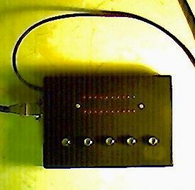
The tiny console is a compact size interface enabling the PC to display various operation status thanks to a 20 LED display witch only uses the standard VGA socket. Furthermore it features a PS2 compatible keyboard able to generate eight character sequencies using 4 control keys plus one "alternate" key. Note that the display and the keyboard can be totally independant from each other and dissociated, even if I present a compact device including both.
Is it really an "analog oriented" design as pretended on this site ?
In fact, not really. I decided to propose this solution because it has been very useful for me while making a home MP3 player using an old 486 DX2. Like for any other design proposed on this site, this one uses very common components. The microcontroller used for the keyboard part is the well known PIC16F84 used as well by many software and/or hardware people. It can be programmed at very low cost and many programming solutions are available on the net.
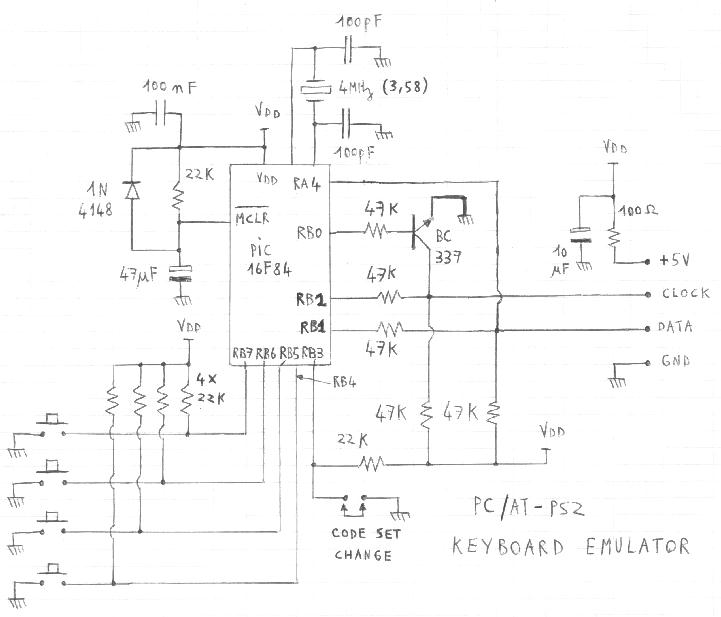
KEYBOARD PART SCHEMATIC
Overview
The circuit will not cause any surprise. The 4 keys and the "code set change" bootstrap (witch is in fact a button like others on my box) have classical pull-up resistors, the reset circuit is a standard RC circuit, and the microcontroller clock is provided by a 3.58 or 4MHz ceramic resonnator. Note that the XT/AT/PS2 keyboard bus always consist in two open collector lines: one clock and one bidirectionnal data line. The principle is close to the I2C's but the protocol is quite different. For details you can refer to Adam Chapweske's excellent website describing accurately the dataframes witch are transmitted on this bus. In that case be careful about the trick that the author uses by using directly the microcontroller I/O's as open collector ports thanks to a change of direction register setting. I did not choose this way to proceed to avoid any hardware destruction in case of crash (never say it will never happen...). That's why only RA4 is directly used as open collector output, simply because it is really an open collector output.
The software source file is available here and uses routines adapted from the Adam Chapweske's code samples. This keyboard acknowledges every command coming from the PC, even if it does not care (e.g. caps lock, various typematic configurations...) and it correctly responds to BIOS start-up test requests. The character strings sent by the keys are the following (then can be easily changed into the source file):
- Key 1 = "R" + Enter, Key 1 + Key 5 = Backspace
- Key 2 = Escape + "E", Key 2 + Key 5 = "P"
- Key 3 = Escape + "B", Key 3 + Key 5 = left arrow
- Key 4 = Escape + "F", Key 4 + Key 5 = right arrow
Note that "Char1" + "Char2" means that this produces the same thing as if the following was done on a classical keyboard:
Press "Char1" and release, then press "Char2" and release.
This character strings have been chosen to match with the configuration I used:
- Mpxplay as software MP3 decoder from PDSoft, running under DOS
- The console manager R.EXE that I wrote to run Mpxplay so that it can be easily controlled with the tiny console (especially for the display). The source of this software is supplied and discussed further in the display part, as well as QB45 routines witch are usable for any other application using the console.
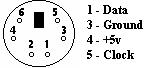
KEYBOARD SOCKET PINOUT
The 4 lines (2 for power supply and 2 for the bus) are connected as follows, when the PC female socket is looked at from the outside of the PC:
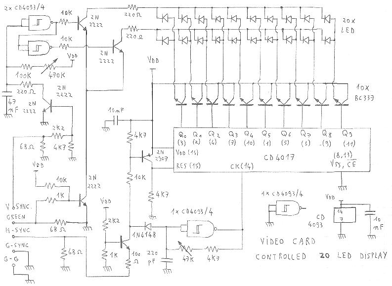
DISPLAY PART SCHEMATIC
Overview
In fact this display could be considered as a 20 pixel video display (two lines x 10 columns) actually reproducing the picture generated by the video card. For that the application software will have to set patterns featuring big white rectangles at locations corresponding to the LEDs to be set on. Note that this display should be compatible with a lot of refresh rates, even if I just used it in standard VGA mode. (There is no use to operate with high resolutions !) Of course, once the settings have been done for one refresh rate, the display will operate correctly only for this one, unless new settings are done on the two adjustable resistors.
How does the circuit work ?
Each one of the two LED lines is activated separately so that the upper one is active (commom cathode pulled to ground via 220 ohms) during the first half of the vertical sweep and the lower one is active during the second half. The simple monostable (adjusted to the half of the sweep time) is trigerred by the vertical synchro V-Sync. The horizontal sweep is managed by the CD4017 self decoded counter witch selects one LED at a time, each time that its clock (delivered by the CD4093 gate in RC oscillator configuration) rises up. This clock generator and the CD4017 are reset at each horizontal synchro pulse on H-Sync. Then the green video signal enable the LED common cathode grounding when it is high, so that the currently active LED is lit if required.
One particular point:
The LED matrix does not exactly represent the video picture because of the following fact: After each horizontal synchro pulse, a quite long blank time is applied so that the CD4017 has the time to scan the two first LEDs while the video line left border is not reached yet. This cause the third LED to be the first possible active one after a synchro pulse has come. To handle that, a trick has been used into the software routine and in the way to set the device sweep time: Beetween two synchro pulses, the CD4017 clock has the time to provide 11 clock pulses instead 9. That makes the device operate in a particular way: After each synchro pulse, the two first LEDs witch are first scanned can never been activated, so that the generated video picture starts with LEDs 3 to 10. After that the CD4017 has the time to overflow and get back to LEDs 1 and 2 witch can be activated at the end of each frame line. Then the next synchro pulse makes it restart from the beginning. That's why if you operate the software routine or "R.EXE" on a monitor you will see first white rectangles on the right side for LEDs 1 and 2, then rectangles restarting from the left border for LEDs 3 to 10.
QBasic routine to manage the display
The advantage of Basic is that it is quite self explainatory for every people, regardless to the language that each one will actually use. (The other reason is that I only know machine code and Basic...). The proposed routine is intended to display a number beetween 1 and 99 by using the upper line for tenthes (0-90) and the lower line for unities (0-9). Any other way to use the display (by lighting several LEDs at a time on the same line) is possible. This example is only given for information and to show how rectangles have to be located.
The following settings will first have to be done before calling the display routine:
scrh = 190
scrw = 640
bord = scrw * .03
squarw = .08 * scrw
squarh = .45 * scrh
interw = .015 * scrw
SCREEN 2
This set of values will allow the exact rectangle size, spacing and location,
according to the selected "SCREEN 2" mode.
After that, the number to be displayed is put into the "i" variable and this sub can be called:
dispnum:
CLS
diz = INT(i / 10)
IF diz <> 0 THEN
'Tenth display
IF diz >= 3 THEN
ddiz = diz - 2
ELSE
ddiz = diz + 8
END IF
lft = (interw + squarw) * (ddiz - 1) + bord
LINE (lft, 0)-(lft + squarw, squarh), 1, BF
END IF
unit = i - diz * 10
'Unity display:
IF unit >= 2 THEN
dunit = unit - 2
ELSE
dunit = unit + 8
END IF
lft = (interw + squarw) * dunit + bord
LINE (lft, scrh - squarh)-(lft + squarw, scrh), 1, BF
RETURN
Some remarks about the display:
The display will not be sensitive to small characters or signs that may stay on the video picture since such things would cause very short LED activation times, making any visual perception quite impossible.
The use of too large or badly located rectangles will cause two or more LEDs being lit instead of one (with some of them eventually brighting weakly), but anyway you will have to tune the display first before trying to fix any software problem. This is detailed further.
As a monochrome monitor, the display will use the green component. Anyway, by using white patterns on a black background, you are sure to get the best results.
Of course this interface is intended to be used with DOS applications launched at the PC start-up. Don't even think using it with any software running under Windows...
The 220 ohm common cathode resistors (LED line selection) apply for high brightness LEDs. For standard LEDs use 82 ohm resistors instead.
The Vdd 5V supply is taken from the keyboard socket 5V pin since the keyboard and display are mounted into the same box for my console. If you decide to get them separate, you will have to find a +5V power supply in another way.
VGA SOCKET PINOUT
The used lines are connected as follows, according to the standard DB15 pin numbers:
- 2 = GREEN
- 7 = G-G (Green ground return)
- 10 = G-SYNC (Synchro ground return)
- 13 = H-SYNC
- 14 = V-SYNC
Setting up and checking
After you checked that the power supply is OK, ensure that the following pins are in the correct state when no PC is connected to the VGA socket:
- Pin reset (15) of CD4017 is high
- Pin CK (14) of the CD4017 is stable and high
- The upper line 4093 gate output low
- The lower line 4093 gate output is high
Then just plug the PC video to the display whith a black picture in the refresh rate of your choice. First turn the 470K trimmer of the line selecting circuit (monostable) while looking at one of the gate outputs with an oscilloscope. You will have to get a 50% duty cycle for this square signal.
For the second setting (CD4017 clock 47K trimmer), it would be better to have the possibility to use the reset pin (15) as trigger source for the oscilloscope. The pulses coming on this pin will cause a blank period in the clock signal (pin 14) witch has to be viewed. Then you must get a 11 rising edge pulse packet beetween two blank periods at high state (for the reason explained above). This will be achieved by adjusting the 47K trimmer. If you cannot use an external trigger source on your oscilloscope, try to do this adjustment while uncalibrating the time base to get the capture as stable as possible.
After you made this settings, you can try to generate some patterns to control the LED display, by using the same rectangle size and space ratios than in the QB source given in example (or by using this routine if you operate in the same video mode). Eventually you will then have to fine tune the LED 2 position (upper and/or lower) with the 47K trimmer (they are the last scanned LEDs just before the next horizontal synchro comes).
APPLICATION TO AN MP3 PLAYER
If you are interested into using R.EXE and mpxplay.exe to turn an old PC into an MP3 player ("old PC" means at least a 486 DX2 at 75MHz with a SB compatible soundcard), you might want to get this source file of R.EXE that will show you how this simple software works. This will allow you to improve it by adding features (playlist randomization, error handling, playlist self update, additionnal controls...). This software is given only for guidance and does not pretend to be a fully achieved product. To test it you will first have to put a few MP3 files on the hard disk (same path as the EXE) and to edit a playlist with any text editor:
On the first line type the number of MP3 files that will be included, then on each following line type the complete DOS 8 character filename (with extension) of an MP3 file to be played (i.e for a number N, there will be N filenames on N lines). Do not insert comments or empty lines. Then save this file as "playlist.txt" in the same path than the MP3 files. You are now ready to launch the application. The keyboard key assignment given above allow you to get the following controls:
- Key1 launches R.EXE ("play" command)
- Key2 exits R.EXE ("stop" command)
- Key3 skips to previous song ("REW" command)
- Key4 skips to next song ("FWD" command)
While a song is played, key5 in combination with other keys provides the following features:
- Key1 restarts the song from the beginning ("re-play" command)
- Key2 is the pause
- Key3 scans back
- Key4 scans forward
Note: In the given source file mpxplay is called in mono mode to be able to run on a 486 DX2 at 75MHz. You can run it in stereo (see author's readme files) but in that case you must at least use a 486 DX4 at 100MHz.
Components alternative
If you don't succeed in finding the transistor or IC references specified in the schematic, you'd have to take care of the following parameters for alternate components:
- BC337: NPN, Icmax > 50mA, Hfe > 60
- 2N2222: NPN, gain-bandwidth above 100MHz, Hfe > 80, Icmax > 50mA, switching transistor recommended
- 2N2907: PNP, gain-bandwidth above 100MHz, Hfe > 80, Icmax > 50mA, switching transistor recommended
- PIC16F84: PIC16C83, PIC16C84, PIC16F84A.
- The PIC source file is fitted for a 3.58MHz resonnator. For 4MHz apply the modifications as indicated into this source file.
Note: CD4017 and CD4093 can of course be HEF40XX or other compatible CMOS without particular restrictions.
Would you want to see other stuff like this ?
Return to HOME PAGE
Сайт создан в системе
uCoz