Simple Digital Geiger Counter
Not requiring the use of any LCD but useable as a standalone device.
Also allows accurate digital data acquisition
The simple galvanometer display provides simple and stable readings.
RETURN TO HOMEPAGE
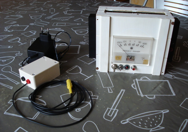
This Geiger counter design presented here is compatible with many types of GM tubes having a recommended operating voltage ranging from 300V to 600V. It requires no other exotic component than the GM tube. It can operate with a 9V battery pack to be used as a handlheld device.
How does a Geiger counter works ?
Many literature can be found about the internet about the basic principle of radioactivity detection by the Geiger-Mueller (GM) tube. If you are not familiar with the GM tube theory you can refer to these interesting websites:
Geiger Counter Design (Website from the "Gamma Scout" Company)
Video from www.chipdip.ru which explains well the principle of GM tube
Exercises with a Geiger Counter from the Northern Virginia Community College
And finally, for people who cannot find GM tubes, this very interesting article from Yasuyuki Onodera about a full home made Geiger counter, including a home made GM tube.
As you can see in the above listed documents, depending on the GM tube that you use it will be possible to detect only gamma particles, or gamma and beta particles, and more rarely alpha, beta and gamma particles. Even if the GM tube is sensitive to several types of particles, it is not able to discriminate these different types. For the most part of the "usual" cases you won't have to place specific shields in front of the tube because detecting simultaneously gamma and beta particles is still efficient to detect any eventual abnormal radioactivity level. However, for analyzing suspicious samples (e.g. food) appropriate conditions are required to reduce the ambient background radiation level. Refer to this synthesis that I've prepared for this purpose.
DISCLAIMER
This project involves high volatges up to 600V. Therefore it is expected that you are experienced enough to apply the relevant care to protect yourself against electric shocks. You engage your own responsability by taking risks during the test and use of the hardware presented on this pages.
SCHEMATIC
Overview
As many other designs, the high voltage (HV) power supply used to set the GM tube in the middle of the plateau region is based on a step-up transformer followed by a one-stage "diode pump" for voltage doubling (also known as a one-stage "Cockcroft Walton circuit"). This provides the advantage of being able to use any general purpose transfomer initially designed for transforming 220VAC into 6-9VAC. We just have to use it reversed. The poor transformer efficiency when used in this way is not a problem at all because the needed current is very low. The more particular feature of the HV generator is voltage regulation. For keeping the GM tube bias voltage as constant as possible when batteries are ranging from 9.5V to 7.5V while avoiding the use of high voltage zener diodes(1), the step-up converter features a regulation loop which automatically adapts the duty cycle of the transformer driver to compensate power supply voltage variations. Potentiometer "HV Adj" allows adjusting the regulated high voltage depending on the GM tube specifications and on the transformer characteristics. It is better to tune the HV generator before connecting the GM tube anode to avoid permanent triggering due to overvoltage. (This could reduce the GM tube lifetime). The ideal way of tuning is to use a variable regulated power supply and check that the GM tube voltage stays near the middle of the plateau region when the power supply ranges from 7.5V to 9.5V. Some variations might be noticed, but they must be compliant with the GM tube requirement sheet. If the compensation is not strong enough, the 120K resistor biasing the feedback point "TP" with Vpp can be changed for a lower value(2). If the compensation is too strong (inverse effect) the same resistor has to be increased(2). More generally, before tuning the HV generator do not forget to mount "Rd" with the appropriate value(3).
The pulse counting system is based on a switching transistor (2N2222 with its filtering capacitors) and on the PIC16F84 which not only counts pulses but also drives the buzzer (one pulse on RB0 induces one toggle on RB7). This allows us not to use an additional buffer (logic gate or comparator) for this task. If no microcontroller is wanted, the analog part of the design can remain used but a buzzer driver must be added, as well as a signal shape sharpener for any counting by another external device.
In the variant of mobile device proposed here, the mean of display does not require to buy a specific LCD which might be hard to find. A simple galvanometer is directly driven by the microcontroller by the mean of a duty cycle modulated signal passing through a low pass filter. Your galvanometer might require more or less current. This is why the low pass filter resistor marked "4K7" might be decreased down to 1K5 (as shown in brackets) if you don't succeed in getting the pointer at its maximum when adjusting the potentiometer "Scale Adj" (detailed further). Depending on the selected scale (switch "SCALE" on RA2) the galvanometer can show a linear or logarithmic response to the count rate (See the scale aspect of my galvanometer to adapt your logarithmic graduations to the conversion law). The count rate is continuously measured over 10 second periods. Therefore the value displayed by the galvanometer is refreshed every 10 seconds, when the LED connected to RA4 flashes. This combines the simplicity of an analog display with the stability and repeatability of a true digital counter. In linear mode, the maximum galvanometer deviation (duty cycle at 100% and potentiometer "Scale Adj" properly adjusted) corresponds to 25.5cps (1530cpm). In logarithmic mode pulse counts ranging from 0.1cps to 1500cps (over a 4,5 decade range) can be displayed. Depending on your GM tube characterized sensitivity, you can also graduate the galvanometer in units of your interest (Becquerel, Curie, Roentgen/h, Gray or Sv/h...)
For accurate measurements of low level radioactivity, pulse counts over a time interval of more than 10 seconds are expected. For example the averaging of several 10s measurements or the counting over a global 3 minute period can be necessary (refer to the prepared synthesis). This is why a serial data output is available on RB6. For connection to a computer this 5V level signal has to be translated to RS-232 voltages (+/-9V min) by using for example this interface(4) also usable as a regulated power supply for the Geiger counter when it is not used as a mobile device (See an example of construction). Note that the device sends actual serial data and not just countable "dummy bytes". Therefore any simple computer program can easily handle the generated true data streams at 1200 bauds, whatever are the operating system and the realtime constraints. To obtain details about the format, as well as example programs (source codes and executable files for DOS/Windows/Linux), you can download this archive.
Notes:
(1) High voltage zener diodes are not so common, and furthermore their power dissipation can easily reach 1W when only biased at 2mA.
This is not only a dissipation problem but also a waste of energy from the batteries.
(2) After having eventually changed the resistor, potentiometer "HV Adj" must of course be adjusted again.
(3) Measure the DC resistance Rdc of the transformer primary coil (former secondary coil in its planned use) and apply Rd = 6.Rdc
(4) If using very old PC computers (e.g. 286, 386...) voltage levels required on the RS-232 line might be more than +/-9V.
In this case you may have to use another kind of interface circuit than IC MAX232.
Note about the GM tube serial load resistor "Rp":
Respecting the GM tube manufacturer's recommendations is very important to ensure a correct lifetime. If using standard 0.25W resistors for that purpose, split Rp into two equal resistors Rp/2 in series. This is not a problem of power dissipation but a question of maximum allowed voltage per resistor to guarantee a correct insulation.
Example for the russian GM tube SBM-19 that I use: Typical load resistor of 10 Megohms specified => Minimum 2 x 4.7Meg in series.
Construction details
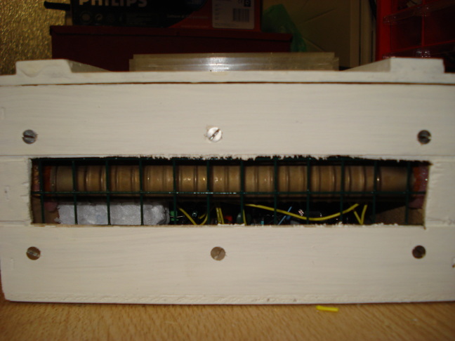
As it can be seen on the schematic, the high voltage components surrounded by a dashed line delimiting the "HV part" area shoud be mounted preferably out of the main circuit board. This guarantees a better insulation resulting in a safer use and in the absence of leakage currents which could exist between adjacent circuit tracks and might cause functional problems, taking into account this kind of voltages. Therefore the HV part is connected to the main board via 4 signals: Ground, point "TP", transformer output, and GM tube cathode. Here is my example of implementation:
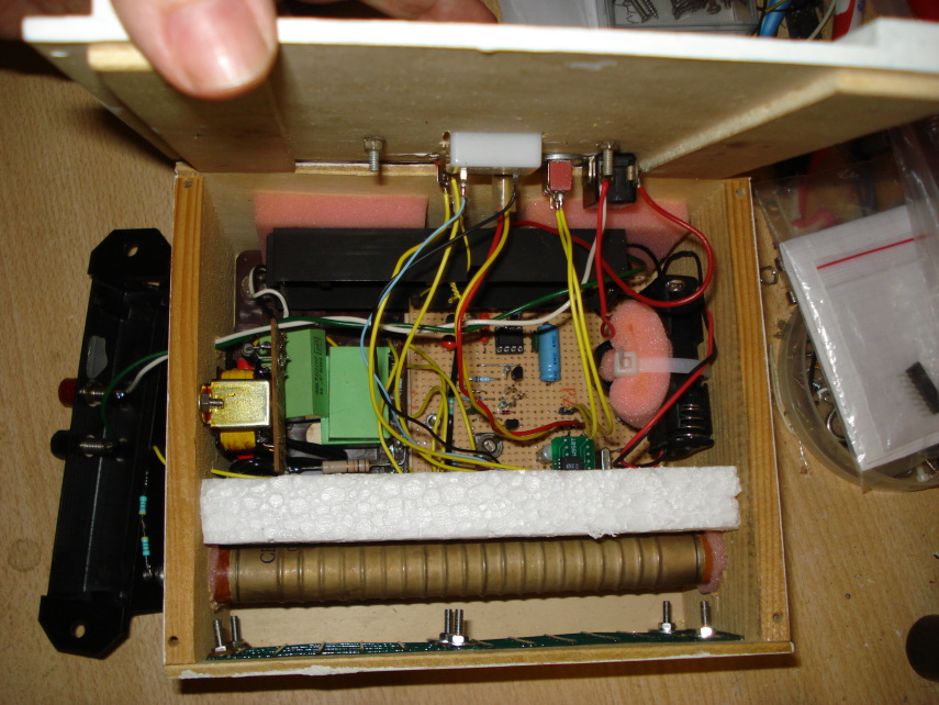
The HV components can easily be seen on the left side of the box (as viewed on the picture) under the transformer and are welded on an old-fashionned mounting barrette. This provides high insulation. More than two high voltage capacitors can be seen because I did not have 100nF but 47nF capacitors that I had to use in parallel. The small PCB featuring an SMD component (behind polystirene) is simply my available replacement of a DIP18 packaged PIC16F84. It is absolutely not necessary to use this kind of package.
The piece of polystirene is only intended to keep wires away from the GM tube to avoid low voltage circuit disturbance by the high voltage pulses. The wires travelling from the high voltage circuit to the tube terminals are placed so that they form the smallest possible loop to avoid excessive device sensitivity to radio interference (non-ionizing radiations).
I've chosen to put the battery packs inside the box and to mount plugs for an external power supply on the side protecting parts. I've added the protecting parts not only for that purpose but also for hiding the GM tube extremities which are secured by the box itself where the GM tube is hold by a shock absorbing foam:
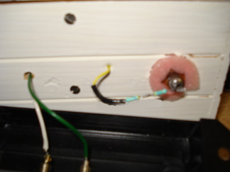
The GM tube terminals are connected to wires by the mean of old springs cut and formed to fit with the situation. Load resistors are located as close as possible to the anode, so that the anode circuit (at very high impedance) is not subjected to radio interference collected by its wire. However it is not guaranted that bringing for example a cell phone close to the device will not cause disturbance such as false counting. But this has nothing to do with radioactivity, although strong non-ionizong radiation is also quite bad for your brain ;-).
Since my GM tube is sensitive to gamma and also hard beta radiations, I've made an aperture in front of it for not stopping beta particles:
The tube is sensitive all along its body. It is not a window GM tube. The efficiency is maximum when incidence of particles is perpendicular to the tube.
Setting up and checking
As previously specified, it is better to adjust the high voltage level before connecting the GM tube. A common digital multimeter able to measure 1000VDC can be used for this measurement. The HV generator withstands a permanent load of 4Meg without dropping down and it is expected that the multimeter set at 1000VDC will show a greater impedance.
It is also better to operate first the device without the microcontroller inserted. (I suppose that anyway you use a DIP18 socket for this component).
When the high voltage output is at its ideal value and correctly compensated, the GM tube can be connected (while the power is switched off, of course!). After connection and power-up, a +5V DC voltage subjected to short negative pulses (50-200us) must be visible on RB0. Pulse occurence must approximately correspond to the specified GM tube background.
Turn "Scale Adj" toward ground and connect a jumper wire beetween pins Vdd and RB1 of the microcontroller socket. Then turn "Scale Adj" smoothly back until the galvanometer pointer reaches the maximum position. The galvanometer is then calibrated.
Switch the power down, insert the microcontroller and restart the device. A test beep must be heard on start-up and the LED must emit two flashes. Then the counting immediately begins while the buzzer produces audible clicks on pulse detections. After the 10 first seconds, the LED flashes once again and the pointer shows the background radiactivity level (small move). Every 10 seconds the pointer position is updated according to the last counting result.
Specific and alternative components - Microcontroller programming
* GM tube: Depending on the country where you live, it might be difficult to buy GM tubes online. I found a quite large choice of GM tubes at http://gstube.com. This russian supplier also ships to Western Europe and US and I've been fully satisfied of the product good condition and delivery time. Among the available products on his website I'd better recommend tubes having a length of more than 15cm, sensitive at least to hard beta radiation, and for which characteristics are available. They are more expensive than tiny and cheap tubes but much more sensitive. This is logical.
These kinds of window-less tubes with thin metallic walls must not be subjected to external pressure. Handle them with care to avoid crushing them !
* Others: If you don't succeed in finding the transistor or passives specified in the schematic, you'd have to take care of the following parameters for alternate components:
- BC337: NPN, Icmax > 50mA, Hfe > 60
- 2N2222: NPN, gain-bandwidth above 100MHz, Hfe > 80, Icmax > 50mA, switching transistor recommended
- Piezoelectric buzzer: Any kind of ceramic disk based piezo buzzer (without built-in oscillator). It is just a question of noise.
- PIC16F84: PIC16C83, PIC16C84, PIC16F84A (other PIC microcontrollers if adapting the source code).
- Crystal: The provided PIC source file is fitted for a 2.097MHz crystal.
You'll have to adapt timer ratios as well the serial transmission routine in case of use of another frequency.
However, if you don't care about serial data, choosing a frequency close to 2MHz keeps the device usable without code change:
=>New linear full scale value on galvanometer = (2.097MHz / Actual Frequency) x 25.5cps.
=>New logarithmic scale on galvanometer: Slightly offset, but this might not be noticeable.
=>New counting interval = (2.097MHz / Actual Frequency) x 10 seconds.
If you have an exact 2.00MHz crystal, I leave this replacement routine to help you in adapting the serial transmission to this crystal frequency.
The ready-to-use HEX file is available, but adapted for 2.097MHz.
Would you want to see other stuff like this ?
Return to HOME PAGE
Сайт создан в системе
uCoz