AUDIO DUBBING FOR VTR
A very particular functionality that is unfindable on the market...
Of course video tape recorders with built-in audio dubbing did exist ! But not in the way exposed here :
RETURN TO HOMEPAGE
People having been experienced in amateur video for ten years probably know what I am talking about. This gear is especially fitted for them, since it will allow an audio post-dubbing on video tapes without making copies or acquisition processes that would degrade the video quality. Note that with recent tools available today for digital camcorders, this system is totally useless. It has been design essentially to process old native analog video recordings, of course ! At this time two types of audio dubbing (or at least the first one described here after) were available when we were buying a VHS VTR designed for amateur video.
The first one was the possibility to record audio after having assembled video clips, over the original sound track. When I say "over", it is really over, so that no more original sound at all was kept. When you operate in that way, even if you don't mind suppressing the totality of the original sound while you insert music for example, things become harder when you want to perform clean sound transitions while returning back to original sound on some clips. Try it if you did not and you will see how it is difficult to do something witch looks professional (or at least of good quality). Furthermore you have no possibility, e.g. while showing landscapes, to mix ambient noises with a background music. That was totally impossible without doing one more copy while passing sound through a mixer (poor video quality !).
The second type available on hi-fi audio VTR's was much easier to use and could provide good results... only when you were reading the tape on a VTR with the same functionality ! While you were assembling your clips, the original audio was recorded on both tracks: classical (called "linear") mono track and hi-fi tracks. While recording, you had to adjust the recording level up and down to prepare clips where the sound had to be kept, mixed, or totally suppressed. It is not so easy to manage that while you are selecting your video clips from the original camera tape. After that, you could record over the classical mono track to perform the dubbing. The advantage was that any error cannot have serious consequences as you could here retry an unlimited number of times, anyway the original sound was kept intact. I'd say hopefully you could ! Since you could not hear the original sound while recording your additional audio (although it would have been technically possible), it was quite difficult to estimate how much recording volume level you had to set along the different clips of your movie. While playing back, you could often be disapointed by the result, e.g. because a background music was too loud compare to the voices, or because the mixing balance with ambient noises was not the one you had planned... When your artwork became statisfying, then you did not forget to activate the mixed audio playback any time that you were showing the movie... That seems stupid to say that, but how many times could hear: "I just showed the movie to my friends today, but the half of the sound was missing, and there were even times where there was no sound at all !". Of course, you always had the possibility to copy the tape and get a true mixed sound on the copy, but in that case there was no gain at all considering the first method.
For sure a lot of people reading this will think that this problem is not a real one, since anyway they will convert their old analog videos to AVI/MPEG files and then re-process them easily. That is true, but in that case you will have no quality analog back-up at all of your work. I am not ashamed to say that today I still back-up my digital native videos (processed by computer of course) on video tapes, in case of further problems with currently used media ! Probably when you'll play your CD/DVD back in ten years to view your prefered family souvenirs you won't be able to read anything (and here I have a quite good feeling to be right...)
You've got at least an old VTR in your attic, even with poor picture quality in playback (this is not critical here), so you may use it for that purpose. (In fact you could modify your high grade VTR but you could have more regrets in case of mistakes...). What I propose here is a small device that has to be inserted on the play/record audio head cable (so you'll have to do some work inside the VTR) and which enable you to record partially over the original soundtrack while adjusting how much you lower the original sound, while viewing the movie, even if the VTR is not suited for audio dubbing. In fact this functionality existed a long time ago, when people where using super 8 or 8mm projectors with built-in audio recorder. Of course, this recording principle won't provide actual hi-fi results, but with good settings and some user experience, it can give totally correct results, considering the sound quality you can get on a classical TV set. Anyway, the original sound on an amateur video camera tape is picked-up in conditions that does not comply with professional hi-fi considerations, even if the analog hi-fi or digital audio track offers a 100dB signal to noise ratio and a 20KHz bandwidth.
Some basis about analog audio tape recording
Some information about analog tape recording is available on the net, but often the sites contain very few details, so that it took me a lot of time finding how to proceed to design this quite simple stuff. Some are completly wrong, stating that audio analog recording consists into the recording of an AM modulated carrier. Finally I did measurements on a running VTR in recording mode to check and compare all different (and opposite) statements that I read on the subject:
Today's prefered method (because of the recording quality) for linear recording is called ''AC bias'' and consists into adding the audio signal with a higher frequency CW sine wave (5 to 10 times the highest frequency of the required audio spectrum). This is done according to the following rules:
- The AC bias current into the recording head has to be high, considering the expected average audio signal current amplitude. Else it is not effective.
- The audio signal amplitude cannot be too great to avoid distortion caused by a non-linear response (while it has to be high enough to keep a correct signal to noise ratio).
- As the recording head is an inductor, its impedance is much higher at the bias frequency than at audio frequencies. That makes the voltage ratio beetween the bias and audio signals to be very high: typically 20-30V pk-pk as AC bias voltage (frequency around 100KHz) and less than 200mV for the audio signal maximum amplitude (measured on a 20 years old Telefunken VHS VTR). This values could vary from a VTR to another but will be quite in the same range (depending on the head itself).
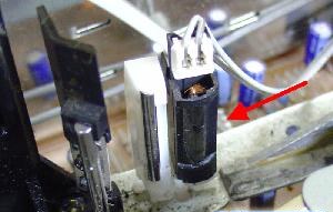
- Before travelling in front of the audio recording head, the tape has been systematically erased by another head (erasing head, since that is its name) supplied with only the AC bias signal, with a higher strength than these of the recording head. In fact the main purpose of this erasure is not to suppress an eventual previous recording (although a low residual signal would subsist after recording if no erasure where done) but to put the tape in its optimal response condition, especially if it has never been used. (In that case, it would be impossible to record correctly without erasure). In VTR not suited for audio dubbing, the erasing head erases all the tracks on the tape in the same time, including video. That's why it is located far from the audio heads, since the tape has to travel in front of it before coming around the video drum (note that video and audio hi-fi recordings use a totally different principle).
- After recording has been done, the audio track could have been played with the same head than for recording (as in audio cassette decks). But in VHS VTR's it is done with another head located in the same "control head" housing (this will be an advantage for us). Of course the signal picked on playback is very weak, considering the audio signal that has been provided to the recording head.
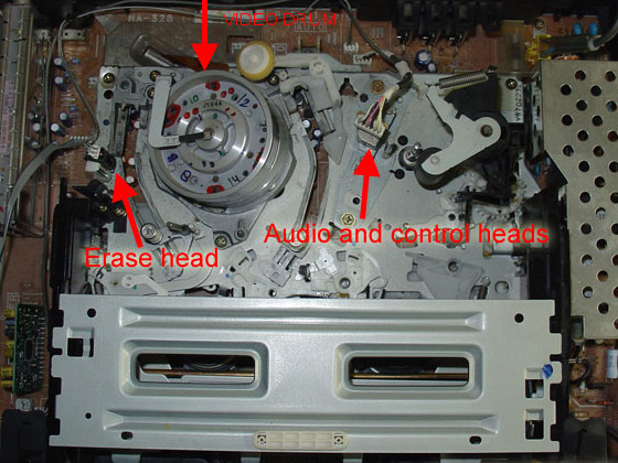
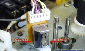
View of the "control head" featuring synchronization View of the large single erasing head
R/W and audio R/W heads)
- It is not possible to do a full true erasure and the recording with the same head (by boosting the AC bias signal on recording) because in that case the tape response becomes bad, especially for the high part of the audio spectrum (trebles). But it still be possible to record over a pre-erased (so pre-recorded) tape without re-erasing it while getting the previous audio signal very strongly attenuated, as well as quite intact. This possibility is never used on VTR's but it is the key of our solution. In that case we have to generate an amplitude adjustable AC bias signal on the recording head, while the VTR is in playback mode.
Interested about ? So let's have a look !
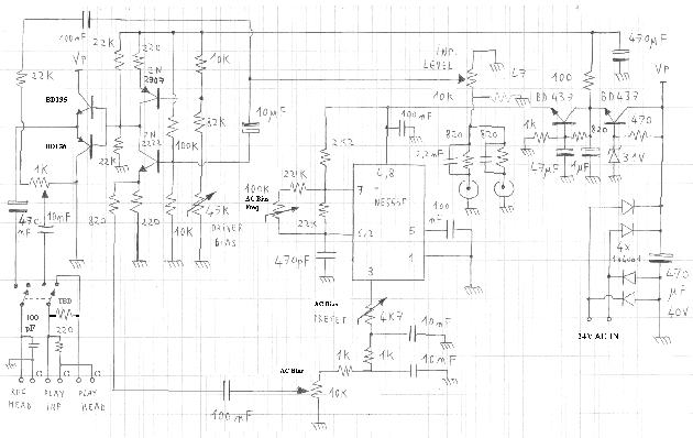
Usually, recording and erasing head driver circuits in audio recorders have a totally different design than the one exposed here, since they are suited for one exact type of head featuring a defined impedance, a recommanded operating voltage and s.o... That is why traditional head drivers are featuring tuned transformers providing high output voltages and an easy coupling with the audio signal circuit. But as the proposed circuit is intended to fit to all types of VTR, it has been designed as a broadband linear push-pull driver (i.e like an audio amplifier output stage) operating at a quite high supply voltage (i.e around 30V). Therefore the bias frequency, the bias amplitude, the audio recording level and the audio monitoring level can be ajusted over a wide range.
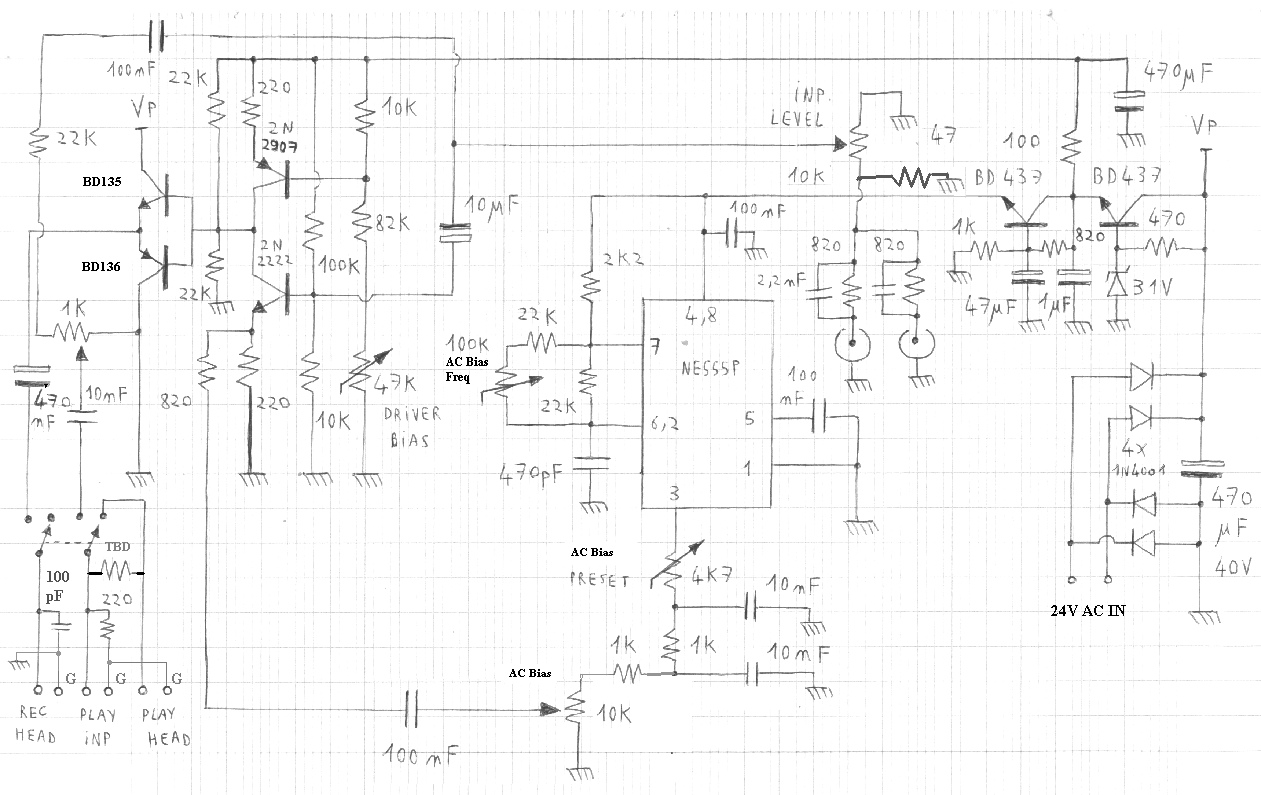
Click on the schematic to see an enlarged view
DISCLAIMER
As you have to work inside the video recorder to proceed, you are warned about the risk of electrical shock that exists. That means that if you decide to pass through the recommandations of the appliance manufacturer, you consider that you are able to take the relevant care that applies for such actions, as would do a professional (especially by avoiding any contact with mains power supply components). In no case at all could I be hold as responsible for individual injury or VTR dammage resulting from any attempt of application of the content of this website.
Circuit overview
As it can be viewed, the sine wave AC bias generator is the essential part of the circuit.
The circuit inserted on the playback and recording head lines features:
- The driving oscillator around the very usual NE555, allowing an easily adjustable frequency. The output pin 3 provides a square wave signal witch is low pass filtered and limited to a defined maximum amplitude limit by ''AC bias preset''. Then the resulting signal is used to drive the output stage with a user adjustable level, thanks to the ''AC bias''potentiometer.
- On the upper right corner, the power supply regulator and the active filter. The first ballast transistor following the zener diode roughly stabilizes the supply voltage of the output stage, then the second one works as an active filter witch suppresses low frequency residual noise while bringing the initial supply voltage to a growth complying with the NE555 specifications. The signal generated by the IC has to be free of any kind of spurious low frequency signal (e.g. mains frequency).
- Two audio line inputs suited for a headphone stereo output (e.g. pocket cassette player) mixed together (with a pre-emphasis) and providing the audio signal to the output stage via the ''Inp. Level'' potentiometer, and to the VTR ''play input'' line via an adjustable resistor for record monitoring.
- The output stage using a transconductance preamplifier stage (2N2907 and 2N2222) and a following emitter transistor pair (BD135 and BD136). The 2N2907 operates as a current source and the 2N2222 uses it as a collector load. The ''driver bias'' adjustable resistor allow setting the biaspoint at the half of the output stage supply voltage. Then the complementary pair following it just lowers the output impedance to drive the recording head. Although this last stage is not linear at the current zero crossing point (no biasing current in the output transistors), this is not critical because the tape itself is totally non-linear in that period part. What has to be taken into account is the current signal peaks (low and high) where the response of the whole system has to be linear, since the added audio signal does its effect there. Anyway the 100pF capacitor put in parallel at the output suppresses any spurious glitch that might have occured at the current zero crossing point.
- The mode selector at the lower left corner using a bipolar inverter switch. Here the circuit is drawn in normal mode (no dubbing): The playback head is directly connected to the ''play input" line (as it was always the case without our system), and the recording head is disconnected. (In fact the VTR original head driver might have been connected to the switch terminal left free, but this depends on where you will place the system, as we'll see further). In the other mode (audio dubbing mode), the playback head is disconnected and the ''play input'' switches to the monitoring attenuator (with pre-emphasis). Furthermore the recording head is then driven by the output stage.
Note that only the ''AC bias'' and 'inp level'' potentiometers have to be used once the circuit has been set up. Therefore all other ones are adjustable trimmers on the board. A particular care will have to be taken for the layout of the ground lines: the ground connections of the power supply reservoir capacitor, these of the regulator and active filter, and these of the output stage must have the less impedance as possible beetween them, and the diode bridge rectifier outputs must be connected directly to the reservoir capacitor terminals. If you are not especially experienced into board layout design, a quite easy way to guarantee a good result is the following: build your board (e.g. ''veroboard'' with pads) without routing the ground lines, except for very short links beetween component ground terminals. For each equipotential point (where ground is therefore missing) obtained in that way, let one component pin not cut. Then when you are finished, use a copper covered board (board for PCB's bought without sensitive resin) as ground plane that you will put 5-8 mm under your component board. Solder each uncut component pin to this plane, as well as the audio input and recording head grounds. This will be much easier if you drill the ground plane, so that you solder on the copper face opposite to the component board side.
Some of you might have noticed some possible issues, such as:
* What happens if the VTR is activated in recording mode while the system is switched to dubbing mode ?
- In fact nothing critical happens (except that you are erasing your video...). The VTR recording driver operates unloaded and the eventually recorded video clip will have a just erased audio track without any sound if the AC bias is turned down. Else you will record at the same time the video and the audio track via the dubbing system (of course it is not the purpose of this system).
* How can I monitor the original sound while I am dubbing ?
- This feature is really available. (In fact, when I did my first tests, I noticed that the crosstalk existing beetween the head and input line cables was already sufficient for a post-monitoring !). For that you will have to adjust, after having put the complete system into real conditions, the value of the resistor ''TBD'' (to be defined). It will depend on the wiring conditions and on the location of the circuit inside or outside the VTR. To do first tests, you can chose R(TBD) = 4K7.
* Apparently the playback head is providing post monitoring audio during the dubbing. How that might sound like if a direct monitoring is active too ?
- In fact it is possible to suppress the direct audio monitoring (by removing the 1K adjustable potentiometer used for that, and its peripheral components: 10nF from the switch, 22K and 100nF from the audio circuit. If you just set the potentimeter to zero, you might have some residual direct sound caused by a common ground impedance). Maybe a lot of users will prefer that way to proceed, because of the ''reverberation-like'' effect induced by simultaneous direct and post-monitoring. However, I found it is useful for music ''pre-hearing'', by putting audio level before applying the AC bias, while viewing the video. Then I know exactly how will correspond the video and music clips at the time when I start the mixed or full dubbing. Note that even in the case of post-monitoring only, I suggest to keep the playback head switch and the R(TBD)/220 ohms divider present, with a 100nF capacitor in parallel with the 220 ohm resistor. This will avoid getting too much high frequency voltage amplitude, induced by the recording head into the playback one, coming into the ''play input'' (not especially designed for that while the VTR is in playback mode). Anyway you will get enough useful audio signal for monitoring. Furthermore, note that keeping only the direct monitoring is not recommended at all, since you could not hear how the original sound is kept or lowered, and the risk to apply improper sound levels with a too low AC bias would be high (causing a distorded audio recording without the possibility to check it).
* What happens if a fast forward or rewind command (while viewing) is activated while the dubbing system is active ?
- Of course you will scratch the audio track all along the rewinded part of the tape. When playing back, the sound will be covered by an ''out of space'' noise or just lowered. So be carefull and don't forget to turn the AC bias down before reviewing your just dubbed movie part...
* I suppose that the recording protection has no effect if someone activates the dubbing system.
- That is true (since our system is absolutely not depending of the VTR recording circuits). So you will have to manage getting the system activation switch not too visible, or to put the system outside the VTR (anyway you might have not enough space to put it inside) with the possibility to disconnect it when it is unused. This will prevent your children or other people from making unvoluntarily bad surprises to you.
* The ''play input'' and the playback head lines have a common ''G'' terminal witch is the VTR preamplifier ground. Why is it not connected to our circuit ground ?
- If you do that, the high frequency current flowing into the recording head will cause a non negligible voltage beetween terminations of every ground return (these of the recording head, but these of the playback head too). This inductive common ground impedance effect can then be added to a localized resistive common ground impedance effect into the circuit, at low frequencies (e.g mains frequency). Even if this spurious voltages are about a few millivolts (witch is very optimistic), this will be higher than a typical playback head signal, and will result into the hearing of a huge annoying noise while dubbing, avoiding you to hear a correct monitored sound. That's why this ground point has to be disconnected from our system's ground. The high rejection of low frequencies provided by the couple 10nF / 220 ohms near the mode switch allow a coupling of the direct audio monitoring line with a sufficiently reduced low frequency noise.
Setting up and inserting the device within the VTR parts
Since heads are connected to the VTR PCB via some cables, it will not be difficult to pick the signals that we are interested in:
Locating the head signals into the VTR
For this you'll first have to operate the opened VTR in recording mode (whatever you record) and of course an oscilloscope (even if it is a 200 Euro model or a 20 years old gear) else don't even think building this system. Particular warning: do not touch the tape while it is travelling along its complex way, else you could induce some catastrophic effects, such as a tape wrapping around the video drum... In VHS systems the audio recording and play back heads, such as the control track signal head (that we will not use) are mounted into the same housing looking like a ''big head'' connected to several cables, and located near the roller/capstan. Here you will have to find and distinguish the recording and audio heads. I suggest to apply this method: while recording is on, track the different signals. You should see one signal featuring sharp pulses with a long interval (control signal that we are not using), and two sine waveform around 100KHz witch are the recording AC bias and the induced voltage resulting from it into the playback head. Do not rely on the voltage amplitude to state witch is the real AC bias signal, but note the both amplitude values, as well as the common frequency.
Now in the second step operate the VTR in playback mode (you will need to hear the sound with the TV or an audio output...) and do this simple test on both noticed head lines: touch the signal lines with a metallic object (while making contact with it in your hands) and you will hear a strong noise in the case of the playback head. Now you can state witch is the recording one and witch is the playback one.
Setting up
After that you'll have to set up the just built circuit in stand-alone before proceeding to its integration. First, on power up, check that the NE555P signal (pin 3) is present and that the supply voltage is correct. Then adjust the ''AC bias frequency'' trimmer to get the same frequency as the one measured on the VTR bias signal. Then while the ''AC bias'' (level) potentiometer is at zero, adjust the ''driver bias'' trimmer to get the voltage at the output complementary pair emitters equal to the half of the output stage power supply voltage. The bias driver is now set up. Third, put ''AC bias preset'' at its maximum resistance value and set the ''AC bias'' potentiometer at the maximum level. While viewing the signal present at the bias driver output, adjust now the ''AC bias preset'' to get 1.2 times the amplitude that you measured on the identified recording head. (If you are limited by the supply voltage on peaks, then set to the maximum than you can while having the signal not clamped). The dubbing system is now operational.
Integration
For this last part I will just expose my way to do, considering that everyone might have his preferred way to proceed:
I first unplugged the head coaxial cables from the VTR PCB (it might be more difficult for some models) and soldered their terminals on pins of a DB9 connector that I could install on the front panel. Then, using new coaxial cables (THAT is NECESSARY), I connected the initial VTR PCB head lines on other pins of the connector, i.e:
- Pin 1 for recording head ground and VTR bias driver ground (common)
witch will be connected to the dubber ground
- Pin 2 for recording head signal input
- Pin 3 for VTR bias driver signal (not connected to dubber)
- Pin 4 for playback head ground
- Pin 5 for VTR playback input line ground
- Pin 6 for playback head signal output
- Pin 7 for VTR playback input line signal
When the dubber is not in use, it is unplugged from the DB9 connector and replaced by a plug containing simple bootstraps as follows:
- Link beetween pin 2 and 3
- Link beetween pin 4 and 5
- Link beetweeb pin 6 and 7
Therefore the VTR is operating exactly as before while this plug is present.
Then when the dubber is used, the connections are the following (in respect to the drawing labels):
- Rec Head: G(G_dubber) = pin 1, switch = pin 2
- Play Inp: G = pin 5, switch = pin 7
- Play Head: G = pin 4, signal = pin 6
Note that pin 4 and 5 are connected together into the dubber and into the dummy plug, but they shall not be shorted together on the VTR connector. Note too that the dubber cable must consist into three separate coaxial cables (one for each of the three links described here above) from the plug to the board. (They can be kept together into a flexible coat).
Components alternative
If you don't succeed in finding the transistor references specified in the schematic, you'd have to take care of the following parameters for alternate components:
- BD135 and BD136: P > 1W, Icmax > 500mA, Hfe > 60 and fT > 10MHz
- 2N2222 and 2N2907: P > 0.3W, Icmax > 100mA, Hfe > 80 and fT > 50MHz
- BD437: P > 1W, Icmax > 500mA, Hfe > 60
- 1N4001: 1N400X (Ifwd > 3A peak)
OPERATING SUGGESTIONS
After having roughly checked with a test tape (e.g. 10 minutes of video recorded on TV) that your system is functional, you may train yourself using it with a maximum of performance and a minimum of mistake risks. (There is no possible dammage, but the risk is about your next precious movie). Depending on your audio source, the high frequency pre-emphasis (2.2 nF capacitors at the audio inputs) might be changed or a series resistor of e.g. 330 ohms can be added for each one. After all is checked OK, I suggest the following steps:
* Maximum volume setting (before each use or after changing the audio source):
As your audio input gets the signal from e.g. a pocket cassette player, you have the possibility to set the player output level. This will be useful to set the maximum allowed audio level, so that you avoid distorsion (distorsion might easily occur if you don't take care to that, especially while you are not already experienced in using this new stuff). So first do a preset test on your already used tape: Put the dubber into dubbing mode while setting the AC bias level and the player level at zero, and setting the audio input level at the maximum. Appreciate the average level of the played sound from the VTR (possible via post-monitoring), then put the audio player on and set the AC bias level at its maximum. Try reaching the same average volume than the initial sound just heard before by adjusting the player output level. The maximum volume setting is ready.
* Balance beetween AC bias and audio level:
To get the additional sound appearing with a better quality feeling, begin putting the AC bias on, then start raising the audio level up just when you begin hearing the original sound lowered. After that the balance adjustment is quite intuitive.
Remarks:
You may have noticed that as the original sound is lowered, the trebles are more affected than the low part of the spectrum. That is the drawback of this system, but sincerely I don't really mind getting this effect, since original sound is always ambient noise or voices and it that case people do not care about this treble lowering (especially when at the same time the music or speaker comment is covering the background sound).
Another thing that you could need is an audio preamplifier and/or mixer to be able to pick the sound of any audio source (cassette, mike, CD...) and to use it directly without first recording on an audio cassette then using the pocket player (or any player with a headphone output). Note that the low input impedance of the dubber do not allow you to connect directly a standard audio line output. You must at least insert a simple small amplifier stage. I think you won't have problems to find that on the net or to do it by yourself. Maybe I will add one on this site in the close future...
Would you want to see other stuff like this ?
Return to HOME PAGE
Сайт создан в системе
uCoz