VOLUMETRIC ULTRASOUND DETECTOR
Using 40KHz transducers and very simple hardware
Purpose of this project
The most common use of this type of detector is probably volumetric car alarms where one piezo-transducer is used as an ultrasound emitter and the other one used as a microphone. Comparison of transmitted and receiver signals allows to detect any change in time of the propagation media: the car body interior.
The goal of the proposed circuit is to provide the same functionality with very simple hardware. Such kind of detector might be used for other purposes like an interactive game, an air flow detector (in a pipe), volumetric detector with another application than car alarm systems.
Basic principle
Many of you know what is called the Doppler effect which applies as well on RF electromagnetic waves as on acoustic waves. In this simplified configuration, the relative move of the transmitter referring to the receiver affects the wavelength of the received wave, just because the wave peaks have a constant propagation speed and the transmitter sends them while moving. Therefore the frequency of the received signal varies with the same ratio: Higher frequency if the transmitter moves toward the receiver, and lower frequency if it moves away.
In the case of our volumetric detector we cannot speak about a pure classical Doppler effect, because the final wave picked up by the receiving transducer is the result of a multipath propagation where any dynamic change in the reflections occuring in the closed volume can lead to a furtive effect which looks similar to the Doppler effect: The received signal changes in terms of phase and frequency (and eventually also in terms of amplitude). Therefore the same type of detector can be used for handling a true Doppler effect as well as for building a volumetric detector where the transducers do not move at all.
The simplest way to detect a phase / frequency change of a received signal versus the initially transmitted signal is to mix them both and extract the resulting low frequency beat. This is exactly what the circuit does. By the term "mixing" must be understood any way of performing a modulation of one signal by another: ideally a mathematical product, and in practice any non linear process allowing to obtain this modulation (such as signal gating, non linear sum, and s.o...)
Circuit design
This circuit is designed to provide triggering pulses to any more or less sophisticated system (from a simple monostable to a microcontroller) when a volumetric change or a Doppler effect is detected. The processing of this pulses is not the subject here, but it can simply be said that taking only one pulse into account is not reliable if building an alarm system. Depending on your application you'll have to develop your own strategy. You will notice that this simple device can be very sensitive and generate significant bursts when someone is simply moving into the room where the test is made.
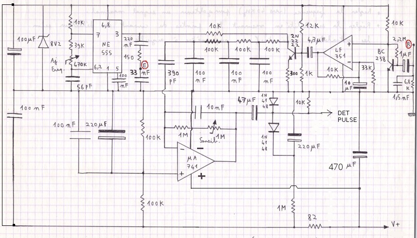
Points "R" and "E" are respectively describing the receiver and emitter hot points. Ground terminals are of course all connected to the device ground. It is expected that standard car alarm transducers are used and operate at about 40KHz. You might succeed into using classical piezo-buzzers out of their expected frequency ranges but not too much above 18KHz. As it can be easily guessed, the frequency is adjusted with the 470K potentiometer connected to the NE555P which is the signal generator. It is better to look for the highest amplitude at the output of OPA LF351 while adjusting this frequency.
It can easily be understood that:
- The signal from the amplifier built around the LF351 is mixed by its output transistor with the signal from the transmitter
- The cascaded RC filters extract the low frequency beat
- The OPA at the bottom amplifies the low frequency beats, up to saturation, so that it provides pulses.
Its sensitivity is also adjusted with a variable resistor (1 Meg)
- The power supply circuit is designed to avoid low frequency unstability in case where the power source has some impedance.
The recommended supply voltage at "V+" is 11V to 14V DC, regulated.
Components alternatives
If you don't succeed in finding the transistor or OPA references specified in the schematic, you'd have to take care of the following parameters for alternate components:
- 2N2222: Icmax > 50mA, Hfe > 80, Ft > 100MHz, switching transistors
- uA741: Any existing OPA able to operate a Vdd-Vss = 11V to 14V
- LF351: Any OPA operating at Vdd-Vss = 7V to 9V, GBW > 10MHz, Slew rate > 8V/us
- 1N4148: 1N914 or any silicium signal diode
Would you want to see other stuff like this ?
Return to HOME PAGE
Сайт создан в системе
uCoz