7W transmitter for 1.5MHz / 3MHz bands
Uses AF transistors and only one tuned LC tank
RF power linear amplifier and its associated input modulator
RETURN TO HOMEPAGE
In the currently presented project it is assumed that you already have a VFO ranging in a frequency interval comprised between 1500KHz and 3000KHz. (In fact you could always get the device working below 1500KHz). Whatever it is sophisticated or not (from the logic gate based crystal oscillator to the PLL circuit) this VFO must be able to provide a TTL level square CW signal with a load impedance of 2000 ohms. Some logic level buffers such as CD4009 might help if this is not the case. Generally you can find good designs of fix frequency or controlled oscillators at the following adresses. This is not an exhaustive list.
Low Noise Crystal Oscillators
Electronic Hobbyist Circuits 2010 (part 2 - LC oscillator)
Stacked Toroid VFO Experiments 2008
Experimental Base Bias Tuned VFO
PIC DDS VFO
How a classical linear amplifier can fit with the needs and what are the benefits
While the required output power is less than a few dozens of watts, the need of having very low losses in the amplifier is not so strong. Considering an expected efficiency of more than 65% at full amplitude with a zero phase load, the choice of a common linear AB class push-pull amplifier is not so silly. Particularly if it can use common AF transistors and low cost standard components.
AMPLIFIER DESIGN AND SCHEMATIC
Circuit overview
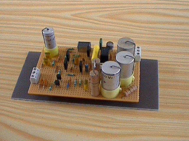
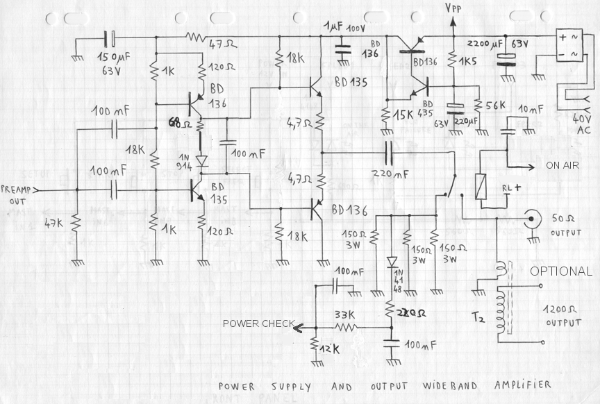
The upper right part of the circuit is the power supply which does not be to be perfectly regulated but absolutely ripple free. This is why the rectifier bridge and tank capacitor are followed by a transistor based buffer providing as output voltage the image of the low pass filtered Vpp voltage. The used transformer must be rated for at least 15VA and you might find a multi-output model where you can couple several secondary windings in series to get approximately 40VAC (RMS). The AB class amplifier is built around 4 common transistors. The output pair (transistors having 4.7 ohm emitter resistors) must be equipped with small heatsinks for being able to dissipate 4W per transistor. The input stage consists in two current sources varying oppositely for driving the AB biased output follower half bridge. The relay and its peripheral componentry (including the 50 Ohm dummy load) are optional and can be use for an easy tuning in locations where no advanced instrument is available. A simple voltmeter connected at "POWER CHECK" allows adjusting the zero modulation carrier level. The relay was planned to allow an automated "ON AIR" control (that I personnaly used). This is a very common 12V relay.
MODULATOR DESIGN AND SCHEMATIC
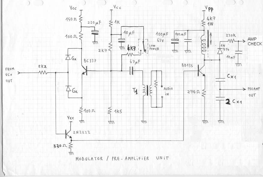
(Vpp comes from the amplifier power supply and Vcc = 5V from a classical regulator)
Circuit overview
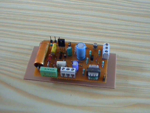
This modulator is in fact more than a modulator. It converts a CW square signal into an amplitude modulated sine wave. To avoid the presence of any audio frequency on output, the first BC337 transistor and its both "Ge" diodes perform a symmetrical peak clamping of the input voltage (versus modulation signal) before it is fed via the 2N2222 follower to the tuned amplifier based on the NPN BD135. Having an audio transformer at the modulation input is not absolutely necessary. However I prefered to use one (small model from an old compact transistor radio audio output stage. Here used in reverse). This allowed to connect easily low level audio sources such as headphone outputs which withstand low load impedances. Then no additional amplifier was needed. I did not specify the value of Cx1 since it depends on the tunable inductor that you will find (recommended between 0.5uH and 70uH). The usual LCW2=1 will help you doing the rest. If you don't exactly know the value of the inductor that you found you will need to do some attempts for finding its value and then the ideal capacitor value. Personnally I found my tunable inductor into a TV from the 70's... You might also use a fix inductor and use a variable capacitor as Cx1 if you have one. But the possible frequency range without amplitude level correction will be tighter because of the output capacitive divider ratio which will vary in that case.
To be tuned the modulator must be loaded by the amplifier input stage. You will probably have to fine tune the bias voltage of the BC337 by changing the 2K7 resistor because the final stage gain depends drastically of the coil quality factor. The ideal is to have the power amplifier output at 70% of its maximum possible level when no modulation is applied. After that you will have to find the correct audio level to achieve approximately the targetted AM modulation peaking at 100%. If changing later the transmission frequency of a few dozen of kilohertz, a simple slight tuning of the inductor might be necessary to correct the output level and the harmonic distorsion by the same way. But if using only one amateur band (1.5MHz or 3MHz) it will not be necessary.
Note that with a tuned antenna this transmitter can show a very good spectral quality (low harmonic rate) while being very easy to re-tune on frequency change. A too high SWR due to a load reactive impedance would also have no effect on the harmonic distorsion but would make the amplifier heat more, as with any transmitter.
Components alternative
If you don't succeed in finding the component references specified in the schematic, you'd have to take care of the following parameters for alternate solutions:
- 2N2222: Icmax > 50mA, Hfe > 60, switching high speed transistors or high GBW transistors recommended
- BD135 and BD136: Icmax > 500mA, Hfe > 60, able to dissipate 4W with heatsink, GBW > 50MHz
- BC337: Any audio transistor or general purpose transistor with Icmax > 100mA, Hfe > 50
- Diodes "Ge": BAT54 or any schottky diode withstanding IF > 50mA and having a recovery time < 50ns, or a vintage detector germanium diode
- Rectifier bridge: Anything that you find able to drain about 1A and to withstand a reverse voltage of 150V (or 4 diodes like 1N4007)
Would you want to see other stuff like this ?
Return to HOME PAGE
Сайт создан в системе
uCoz