CHARGER FOR PRIMARY ALKALINE CELLS
Succesfully tested and designed according to the "Reverse Pulse Method"
Recharge your alkaline cells many times and at more than 80% of their initial capacity !
RETURN TO HOMEPAGE
The discussion about charging alkaline primary cells started a long time ago. The main initiating document appears to be a divulgated internal report (in French) from the former french company "Les Piles Wonder" and dating from the early 70's, unless the letter circular LC965 of the US National Bureau of Standards was published before. At that time the MnO2 cell was a new technology and all the possible benefits had to be investigated. In this report the possibility of recharging alkaline MnO2 cells was studied, with as a result the specification of basic constraints to be applied for recharging moderately discharged batteries (i.e. cells having an unloaded voltage of at least 1.25V). The document also provides a basic charging circuit able to source a constant current to the cell and stopping the charge when the voltage reaches 1.7V. (Don't try to find the specified transistors, they are about 40 years old). This already proved that MnO2 alkaline cells can be recharged like in theory, but with some limitations: some irreversible chemical reactions would happen under 1.25V, impairing the possibility of efficiently recharging the cell. Furthermore, forcing the cell to recharge more quickly with a higher and prolungated current without pauses can induce the production of excessive gases inside the sealed container and then lead to an explosion.
The reverse pulse charging method and the associated patent
A method for improving drastically the recovered capacity even for highly discharged cells has been proposed by Robert S. Feldstein and Pelham Manor (N.Y) under the form of the US patent 5,291,116 published on the 1st of March 1994. This document gives a detailed description of the problems which might occur during the charging of primary alkaline cells as well as the remedy to these problems:
CITATION:

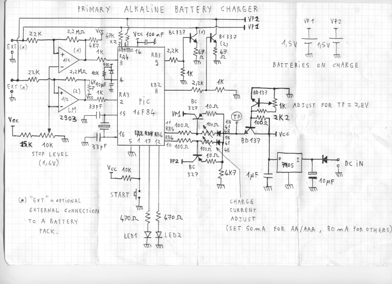
DESIGN AND SCHEMATIC
Click on the schematic to see the enlarged version.
Circuit overview
The whole pulse generation and monitoring process is performed by a Microchip PIC16F84, one of the most common microcontrollers in the homebrew hardware world. The source code as well as the HEX file can be downloaded. (The source code can be easily adapted for any PIC16FXX device). The circuit is designed to charge simultaneously and independently two 1.5V cells. This is why we can notice:
- Two discharge circuits driven by ports RB2 and RB3
- Two charge circuits driven by ports RB4 and RB5 (active at low level)
- Two comparator inputs on ports RA3 and RA4 for checking the unloaded cell voltages along the process
- Two test pull-up resistors on ports RB0 and RB1 for detecting the presence of discharged cells when requested to start.
(No cell present will be seen like a charged cell, and the charging won't start)
- Two LEDs showing that the charging process is running on the corresponding cells.
- One start button read by port RA2
Both BD137 transistors are used as a basic adjustable voltage regulator aimed for limiting the maximum possible output voltage of the current sources as well as limiting the dissipated power in both BC327.
The crystal frequency should be as close as possible to 2MHz if using the program as is, otherwise a tuning of the subroutine "TIMBASE" will have to be done.
The firmware was developped so that:
- The charging pulses are 6ms long
- The discharging pulses are 2ms long
- The rest time + monitoring takes 1.5ms to 2ms
- The long discharge pulse is 1 second long and occurs at every minute.
Setting up and checking
It is best to start tuning the circuit without having the microcontroller inserted. (I hope you mount it on a DIP adapter). Start by adjusting the 1K potentiometer as indicated on the drawing. Then connect a resistive load RL (10 Ohms recommended) instead of each cell, so that it is easy to measure the sourced current without reaching more than 1.5V. Pull RB4 and RB5 down to ground ad adjust both 100 Ohm potentiometers to get a voltage of RLx0.07A in each load (or RLx0.12A for cells bigger than AA). Then it is time to adjust the comparator reference: Turn the 10K potentiometer to get 1.65V on its cursor (negative inputs of comparators).
After having tested that the pushbutton and LEDs are correctly connected and operating, the device is ready for microcontroller insertion !
For using the device, simply connect one or two cells and press the START button. The LEDs corresponding to connected cells will light on. They will be switched off when the charge is finished. Note that the charging time for an AA cell at 1.2V is about 17 hours. It is close to 24h for a completely discharged AA cell (about 0.8V). If doubling the charging pulse currents, these charging times can be cut by two. The charging will remain effective but the process will not be so safe.
Remark: Removing a cell during the charge will not cause an LED switch-off until the START button is pressed once again for refreshing the status.
Components alternative
If you don't succeed in finding the component references specified in the schematic, you'd have to take care of the following parameters for alternate solutions:
- BC337 and BC327: Icmax > 50mA, Hfe > 60, switching high speed transistors not recommended
- BD137: Icmax > 500mA, Hfe > 60, power dissipation 0.8W without heatsink
- All diodes except the one at the 78L05 regulator input: 1N4148 or any general purpose silicon diode
- The diode in series at the regulator input: 1N400X or any rectifier diode withstanding IF = 220mA
- 7805: Any 5V regulator able to source at least 220mA and to dissipate (Vin - 5V) x 0.22A (depends on your input voltage)
Note that a real 5V DC regulated voltage is necessary for correct operation since the supply voltage is used as reference everywhere in this design.
Would you want to see other stuff like this ?
Return to HOME PAGE
Сайт создан в системе
uCoz